An Introduction to the C4 Modelling Language
The C4 model was created between 2014 and 2017 by Simon Brown.
The C4 model was created as a way to help software development teams describe and communicate software architecture, both during up-front design sessions and when retrospectively documenting an existing codebase. It’s a way to create maps of your code, at various levels of detail, in the same way you would use something like Google Maps to zoom in and out of an area you are interested in.
The C4 Model
The C4 model is a modelling language with a few distinguishing characteristics. For instance, the four core diagrams are hierarchical and allow the user to explain a software system using different levels of detail, which optimizes the delivery of the information to different audiences.
The Four Core Diagrams
- Context (highest)
- Containers
- Components
- Code (lowest)
Context
The Context level is the most abstract and shows the least amount of detail. This level shows which users are using the software, which of the systems are external and how the systems interact with your internal system.
This level has been very helpful in my experience when you’re:
- introducing your team’s landscape to a new team member (both for technical and non-technical folk)
- explaining your landscape to a different team in the organization
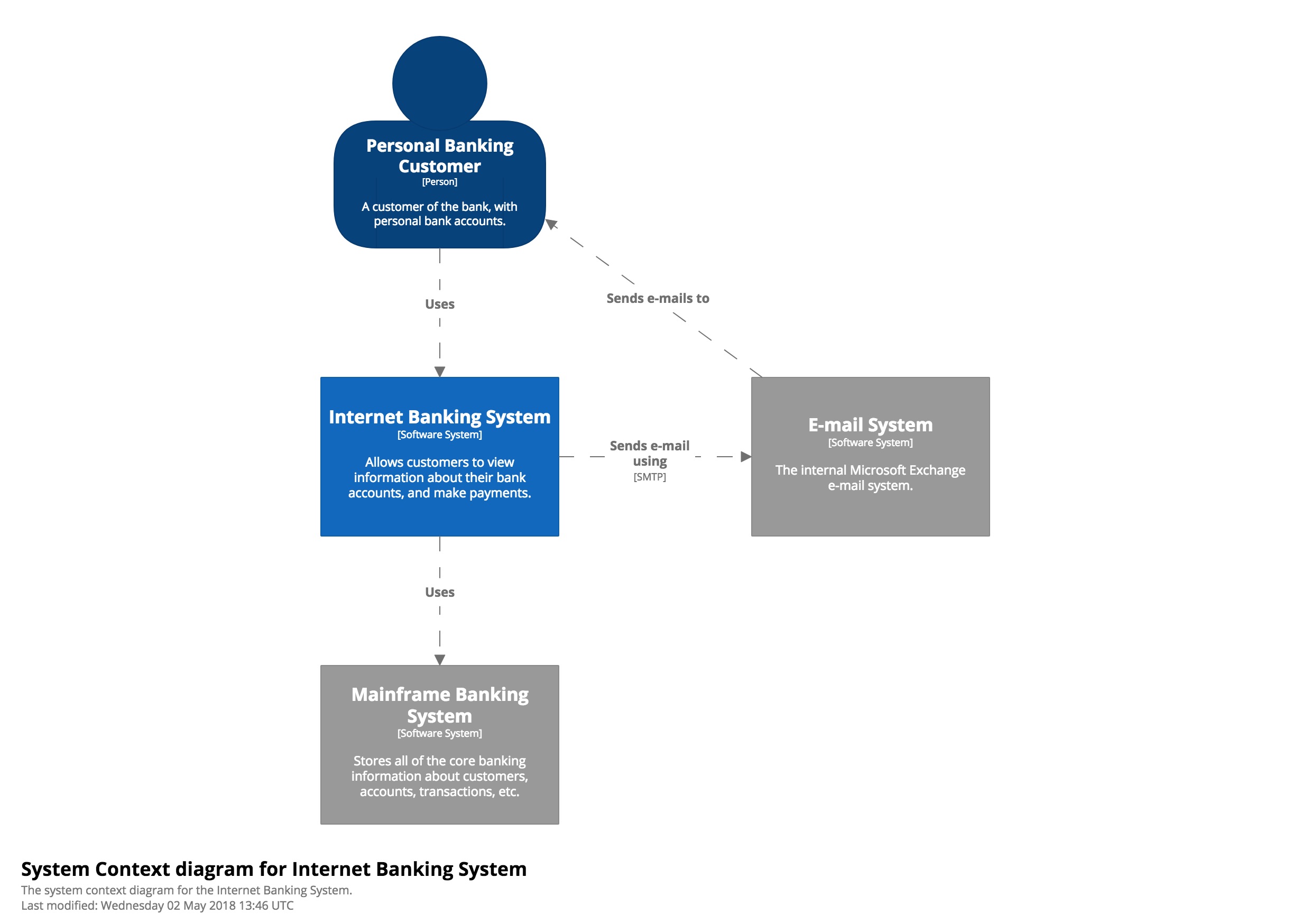 Level 1: A System Context diagram provides a starting point, showing how the software system in scope fits into the world around it.
— c4model.com
Containers
At the Containers level the internal system is no longer mapped as a black box. The internal system is exploded into containers, meaning deployable units (APIs, web applications, mobile applications, database schemas, filesystems, etc.) are shown individually.
The Containers level diagrams can be very helpful during team sessions (e.g. refinements) to get everybody on the same page and to reduce miscommunication. It can also be helpful in onboarding a new colleague, it’s like giving someone a map of a country/region they’re in for the first time. This serves as a tool for collaborating on deciding where the change should be implemented, and how the change should - or should not - affect its up-/downstream dependencies. When I’m new on a team and there are no architectural diagrams, I create the Containers diagram first to map out the landscape. This tends to lead to interesting discussions with other developers regarding the landscape and quickens my understanding of it.
 Level 2: A Container diagram zooms into the software system in scope, showing the high-level technical building blocks.
— c4model.com
Components
The Components level zooms in on an individual container. All users and up-/downstream dependencies (internal containers and external systems) are dropped from the diagram, except for the ones a Component interfaces with directly.
This diagram allows for a lot of detail. I tend to let it depend on the situation whether I choose features, layers or classes as Components. There can be multiple Component diagrams for a Container if that proves valuable. My rule of thumb is: as long as the diagram does its job at explaining the internals of the Container significantly better than opening the solution in an IDE, this diagram provides value. Otherwise, it would only add to the maintenance burden of updating it every time the code changes.
In my experience, this diagram has been mainly helpful when dealing with messy, counter-intuitive codebases. It did not prove valuable when solutions were well designed, small, or were following a clear pattern (such as Ports & Adapters). When creating a Component diagram, start with the composition root, and map all the code paths that go to either up- or downstream dependencies. The rest are probably helper classes and can be left out.
 Level 3: A Component diagram zooms into an individual container, showing the components inside it.
— c4model.com
Code
The Code level removes all users, all external systems and internal containers. Furthermore, it focusses on adding technical depth to a Component. Disclaimer: I’ve never felt the need to create a diagram at this level of detail, since this kind of diagram can be generated from code. For instance, by using a tool that interprets your code base and generates a PlantUML definition of a class diagram.
 Level 4: A code (e.g. UML class) diagram can be used to zoom into an individual component, showing how that component is implemented.
— c4model.com
Further reading
Check out these official resources by Simon Brown.